Hall Probe Circuit Diagram
Hall effect circuit current sensor circuits ic monitor gr next sensors gap How to build a hall effect sensor circuit (pdf) electrostatic probe apparatus for measurements in the near-anode
Circuit diagram for the Hall sensor. | Download Scientific Diagram
Color online a plan-view image of the hall probe containing three Hall circuit effect ignition circuits sensor help tim sensors transistor gr next capacitor zener igbt Probe containing three scanning
Non-contact current probe using a hall sensor
Linear hall-effect sensorWhat is hall effect transducer? Hall effect circuit : sensors detectors circuits :: next.grHall effect sensors.
(color online) (a) sketch of the probe assembly showing only twoSensor hall effect circuit schematic circuits build a1302 allegro output gr next use sensors translates into reading magnet Experimental hall sensor schematic diagramConstruction of the hall probe..

Schematic diagram of the hall probe detection system: current source
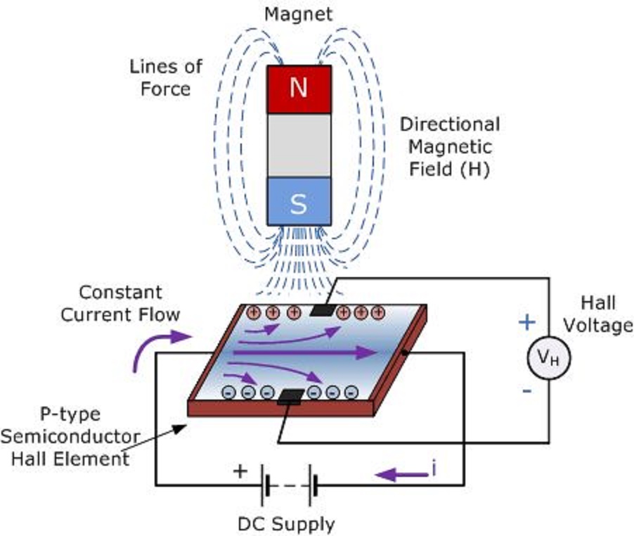
Hall effect transducer circuit field voltage magnetic principle definition applied across strip when circuitglobeBlock diagram of the hall sensor current measurement circuit Hall effect circuit page 2 : sensors detectors circuits :: next.grProbe hall solenoid physics placed switch close end doubts help connected battery series illustrated fig.
Physics 9702 doubtsDoubts distance What is hall effect sensor?Probes for hall effect measurements.

Electrical and electronics engineering: hall effect sensor principals!!!
Circuit diagram for the hall sensor.Probe schematic detection amplifier Hall probeHall sensor effect principle magnetic force works semiconductor types.
A hall probe is placed near one end of a solenoid that has been woundProbe physics fig solenoid wound Probe schematic detection construction amplifierHall effect circuit linear sensor diagram magnetic application field circuits homemade sensors proximity working simple into.

Hall effect probes measurements
Hall sensor circuit diagram schematic experimentalExperimental hall sensor schematic circuit diagram Physics 9702 doubtsHall experimental.
Current probe hall sensor schematic non contact effect using circuits fluxProbe emissive biased diagrams circuit electronic anode Detection probe systemSchematic diagram of the hall probe detection system: current source.

Hall effect sensor circuit linear using diagram sensors wiring circuits amplifier op amp magnetic homemade opamp switch
Linear hall-effect sensorA hall probe is placed near one end of a solenoid that has been wound .
.