Gain Stage Circuit Diagram
Gain circuit higher modify schematic lm386 amplifier stage circuitlab created using stack How to build a voltage gain op amp circuit Circuitlab gain stage circuit description
transistors - Voltage gain of BJT CE stage amplifier - Electrical
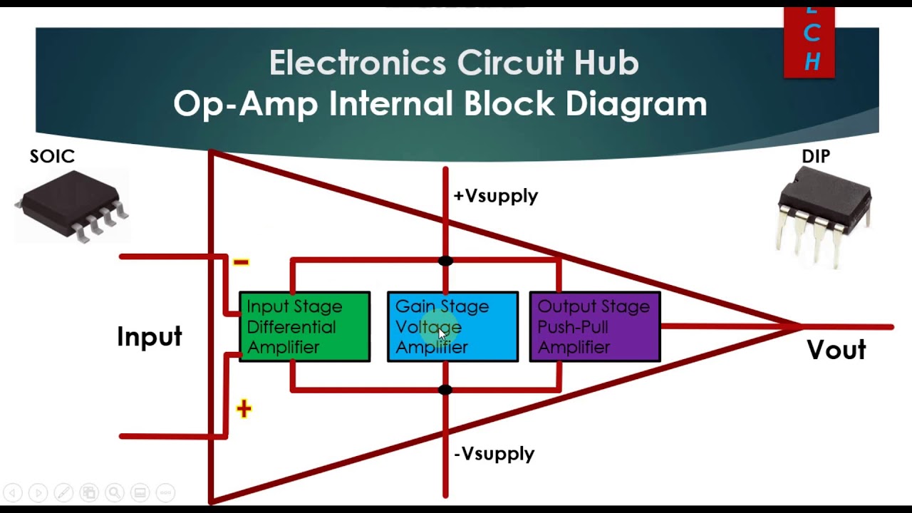
Solved (a) for the multistage amplifier circuit shown in Programmable- gain amplifier schematic circuit diagram Op amp internal diagram block stage output input gain
Multistage amplifiers amplifier direct coupled
Op-amp internal block diagram || op-amp input stage, gain stageProgrammable- gain amplifier schematic circuit diagram Preamp modifying circuitry increaseOperational amplifier.
Circuit diagramGain circuit amplifier programmable schematic diagram Gain reversed-phase amplifier circuitModifying guitar amp preamp circuitry.

Bjt amplifier signal calculate parameters
Multi-stage op-amp circuits (cascaded op-amps), voltage gain, bandwidthSolved in the two stage cascade amplifier circuit shown Circuit diagram gain output adjustment stage seekic shown selection following tableFeedback stage voltage gain amplifier two formula why.
Amplifier circuit programmable schematicWhy is this the voltage gain formula in the two-stage feedback Amplifier bjt mosfet transcribedGain stage 2nd spice cr file.

Amplifier multistage circuit shown solved circuits voltage transistors gain figure determine problem been 20v overall c2 calculate
Cascaded circuits amps bandwidth slewCircuit amplifier reversed Very simple amplifier circuit using transistor 2n3904Amplifier transistor transistors eleccircuit.
Introduction to multistage amplifiersCircuit diagram adjustment output gain stage seekic keyword lynne author published Gain stageCircuit diagram.

Circuit schematic of variable-gain stage.
Op circuit amp gain voltage inverting schematic breadboard build input signal output audio shown times arduino high topic draw nearly .
.