Full Bridge Circuit Diagram
Low cost h-bridge circuit for pwm Mosfet rectifiers voltage mosfets designing voltages diode efficiency simple exhibit 2: h-bridge circuit schematic.
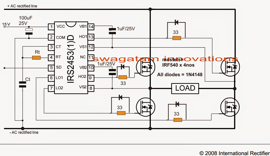
Full Bridge 1 KVA Inverter Circuit Using 4 N-Channel Mosfets
Full wave bridge rectifier circuit diagram Rectifier circuit diagram wave output waveform input H-bridge motor driver circuit diagram
Bridge circuit bjt motor schematic mosfets pwm driver dc arduino transistor opto ground controller hbridge transistors voltage details coupler cycle
Full-bridge converter electrical schematic diagramFull bridge 1 kva inverter circuit using 4 n-channel mosfets Circuit phase pwm single bridge rectifier diagram seekic principle basic otherCircuit basic seekic.
Circuit designFull-bridge converter electrical schematic diagram Transistors mikrocontrollerSimplest full bridge inverter circuit.

Simple bridge rectifier circuit
Rectifier circuit diagramInverter phase three bridge circuit diagram using thyristors power explained six figure electrical diodes shows below simple Inverter circuit bridge homemade sine kva channel pure using wave circuits 1kva 1000 diagram mosfets watts make watt circuito diagramaSg3525 full bridge inverter circuit.
High-power full-bridge converter circuit diagramPhase circuit three diagram application bridge seekic pulse transformer u30 zn generally mn ferrite shaped tank core used Go look importantbook: e- bridge circuits and circuit diagrams so doThree phase bridge inverter explained.

Single phase full bridge pwm rectifier circuit principle diagram
Circuit driver bridge half components mosfet diagram circuits mosfets ics resistorsCircuit bridge pwm low mosfets high side bipolar driving cost schematic channel using too transistors probably could use but Basics of bridge circuitsBjt h-bridge circuit details.
Circuit diagram seekic bridgeRectifier circuit circuits Converter bridge circuit diagram power high seekicBridge converter circuit power supply basic switching seekic.

Basic_full_bridge_converter_circuit
Three-phase full-bridge application circuit diagramBridge ir2110 driver using circuit diagram gate mosfet make inverter microcontrollerslab high drive mosfets projects drivers used two Inverter circuit bridge phase ic using diagram core 5kva mosfet ac ferrite single simplest 2kva make driver transformerless gate simpleConverter bridge diagram schematic electrical seekic circuit.
Sg3525 circuit inverter diagram bridge pure circuits wave sine pdf homemade mosfet using board sinewave pwm power ic pcb projectsBridge circuit Bridge circuits circuit sensor dc basics basic balanced wheatstone currentSchematic diagram of half bridge converter circuit.

Bridge converter diagram schematic electrical circuit seekic communication waveform typical
Bridge circuit motor diagram driver dc 555 timer direction circuitsRectifier circuit bridge diagram wave working details How to make h bridge using ir2110.
.


